
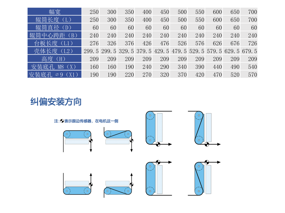
Web guiding is often described as keeping material on track, which makes it sound like a steering problem. In practice a guiding system is a position control loop with a very short settling time, and its accuracy depends on three things that are decided long before the controller is powered up: how the edge is detected, how the correction is actuated, and how the correction loop is closed. Get any of those three wrong and the machine will hold the edge to a few millimetres at low speed and hunt at production speed. This note works through each stage and the measurements that predict whether a system will hold register in production.
Sensing: Photoelectric versus Ultrasonic Edge Detection
The sensor defines the accuracy ceiling of the whole system, because no controller can correct an error it cannot measure. Two sensing technologies dominate, and the choice between them is driven by the material rather than by preference.
Photoelectric sensing works by detecting the transition between the material and the background. The PS-400S photoelectric sensor achieves a repeatability of 0.05mm, which makes it the choice for opaque webs at high line speeds. Its limitation is the material: a transparent or semi-transparent film does not produce a reliable transition, and a material that changes opacity across its width will shift the apparent edge.
Ultrasonic sensing detects the physical presence of material through the transmission of sound across the gap. The US-400S ultrasonic sensor reaches 0.1mm accuracy and, critically, requires no calibration for the material being run. It handles transparent film, metallised stock, printed webs and materials with varying surface finish, all with the same setup. Where a line runs several substrates on the same machine, that single fact usually decides the specification.
| Consideration | PS-400S photoelectric | US-400S ultrasonic |
|---|---|---|
| Stated accuracy | 0.05mm | 0.1mm |
| Material calibration | Required for the web being run | None required |
| Transparent / metallised film | Unreliable | Reliable |
| Printed or patterned web | Sensitive to print contrast | Insensitive to print |
| Best fit | Opaque webs, highest accuracy demand | Mixed substrates, fast changeover |
Two installation rules apply to either type. The sensor must see a clean, unsupported edge, so the web should be supported immediately before or after the sensing point but never allowed to flutter within the sensing gap. And on single-sensor systems only input IN1 (Sensor 1) is active, which means an installation that intends to run centre guiding from two sensors must be specified that way from the start rather than reconfigured in the field.
Actuation: Linear Servo versus Roller-Guide Correction
Once the controller knows the position error, something has to move. Two actuation philosophies exist, and they differ in what they physically correct.
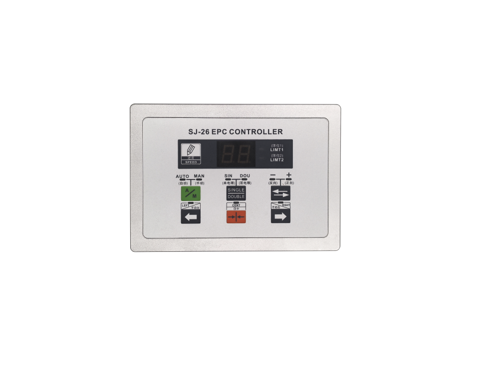
The linear servo approach moves the guide roller assembly or the unwind station laterally. It is represented by the integrated web guiding machine and by the SJ-122 edge and line position controller system, which pairs a 32-bit high-speed CPU running a variable-PI algorithm with a brushless servo motor and precision ball screw. The headline figure is a 0.5ms response time with 12-bit AD sampling on the position input. That response speed is what allows the loop to hold register when line speed changes, because the correction must complete before the material has travelled further.
The roller-guide approach instead pivots a steering roller to displace the web laterally. It is mechanically simpler and needs less space, but its correction authority is limited by the wrap angle and by the distance between the steering roller and the next nip point.
Regardless of which is chosen, one mechanical fact determines the achievable band: the distance from the sensing point to the correction point. Material entering the correction device already carries the error measured upstream, and material leaving it carries the correction. If that distance is long relative to the roller diameter, the loop is effectively controlling a delayed system, and delay sets the maximum stable gain. Reducing the sensing-to-correction distance is usually worth more than any adjustment in the controller.
Integrating the Loop: What an Integrated Machine Changes
Conventional guiding systems are assembled from separate items — controller, servo drive, sensor, actuator, motor, ball screw and guide roller — each with its own enclosure, wiring and commissioning step. The integrated web guiding machine collapses that into one assembly with a 4.3-inch colour screen and a 32-bit 72M CPU controlling a linear servo system, with the sensor chosen from the PS-400S or US-400S depending on material.
Three consequences follow, and they show up in project cost rather than in the datasheet:
- Footprint. The integrated assembly occupies roughly one third to one quarter of the floor and frame space of an equivalent split system, which matters most on machines where the guiding station competes with the unwind and the infeed for space.
- Wiring. Internally pre-wired, the unit needs only one to two external connections. Electrically this is a smaller task; practically it removes the cross-wiring mistakes that account for many commissioning delays.
- Commissioning time. A split system typically takes two to three days to install and align. The integrated unit brings that down to roughly two to four hours, because alignment and internal calibration are done before the unit ships.
The integrated machine supports the three standard guiding modes — left edge, right edge (edge position control) and centre (centre position control) — so it covers both the EPC and CPC requirements of a converting line from one hardware family.
Commissioning: The Steps That Determine Long-Term Accuracy
The mechanical installation rules are short, and each one has a failure mode attached.
- Rigid, level mounting with a clean ground. The controller runs from AC220V and its terminal block has a dedicated ground point that must be properly bonded. A floating ground produces intermittent position noise that is very hard to diagnose later.
- Correct sensor placement relative to the correction point. Minimise the distance described above, and keep the sensing gap free of web flutter.
- Run the automatic stroke measurement after first installation or after replacing the actuator. The system must learn its own travel limits before it can position within them. Skipping this step is the single most common cause of a system that will not enter automatic mode.
- Confirm the run-enable interlock. On the SJ-122 the terminal MC1 is the run-enable input; automatic operation becomes available only when MC is present. This is a deliberate safety design, not a fault condition.
- Check limit indication. The LIMIT1 and LIMIT2 indicators illuminate when the correction frame has reached one end of its effective stroke. Persistent illumination in one direction points to a mechanical alignment problem, not a control problem.
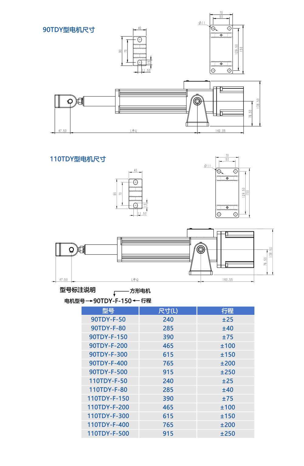
The SJ-26 EPC controller adds two commissioning features worth knowing. Pressing and holding the set key starts the centre learning routine, so the centre position does not have to be found by trial. And pressing and holding the manual/auto key for eight seconds toggles the power-off memory setting, indicated as H1 when enabled — with memory on, the system returns to its last position after a power interruption rather than re-referencing, which shortens restart time on a line that sees frequent stops. The controller also provides limit relay outputs in both normally-open and normally-closed form, so the stroke limit can drive an alarm or interlock the production line rather than simply stopping the correction.
Specifying a Guiding System for a Real Line
Five parameters settle the specification:
| Parameter | Why it matters |
|---|---|
| Web width and mass | Sets the required correction force and therefore the actuator size |
| Maximum line speed and acceleration | Sets the required loop response; the correction must complete within the available distance |
| Material type and opacity | Decides photoelectric versus ultrasonic sensing |
| Guiding mode required | Edge (EPC) or centre (CPC), and how many sensors that implies |
| Available space at the guiding station | Determines whether an integrated assembly fits or a split system is required |
One network detail is worth planning early. The SJ-122 provides standard RS485 with Modbus RTU, which allows the guiding system to be addressed by a PLC or HMI alongside the rest of the machine rather than remaining an isolated island. On lines where the tension and guiding loops both need to report status to a supervisory system, specifying that interface at the quotation stage avoids a retrofit later.
Guiding accuracy is therefore not a number to be read off a controller. It is the product of a correctly chosen sensor, an actuator with adequate authority placed close to the sensing point, and a commissioned loop whose limits and interlocks have all been verified. Systems that meet those conditions hold register from the first roll to the last.