Two machines can carry identical tension controllers, identical brakes and identical web material, and still deliver different product quality. The difference usually sits in the signal chain between the load cell and the controller input: the amplifier, its scaling, its grounding, and how the resulting signal is treated by the control algorithm. This note explains the signal chain in a tension control system, what the analog and digital controller families each do well, and the measurements that let an engineer verify a delivered system rather than assume it.
The Signal Chain from Web to Controller
A tension measuring system converts a mechanical force into a usable control signal in four steps, and each step contributes its own error.
- Force to strain. Web tension acting on a measuring roller produces a force at the load cell. The cell converts that force into a small differential voltage, typically millivolts.
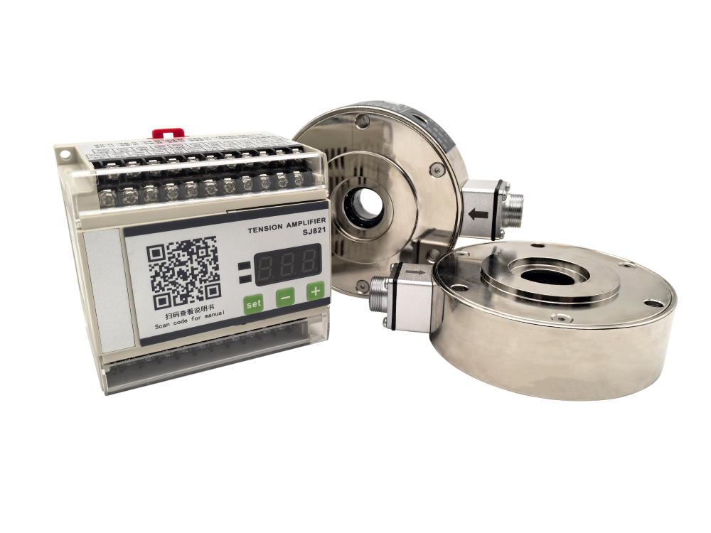
- Strain to standard signal. The tension amplifier excites the bridge, amplifies the differential output, filters it, and scales it to an industrial signal level. On the SJ-821 amplifier the output is 0–10V or 4–20mA, chosen by parameter, with supply at 220VAC ±10%. Two input channels are provided.
- Standard signal to control variable. The controller reads that signal, compares it with the setpoint, and computes an output.
- Control variable to torque. The output drives a clutch, brake, inverter or servo, converting an electrical command into mechanical resistance.
Error introduced in step two propagates through everything downstream. This is why the amplifier deserves the same attention as the controller, and why the sensor rating has to be chosen against the actual working tension rather than against the machine's maximum.
Choosing the Sensor Rating
The tension sensor range is selected from 15KG, 30KG, 50KG or 100KG, with bearing bores of Φ17mm or Φ25mm, both available as customised variants. The selection rule is not to pick the range that comfortably exceeds the maximum tension.
A load cell's usable resolution is a fraction of its rated range. If a process runs at 8KG but the sensor is rated at 100KG, the working point sits at less than a tenth of full scale, and the signal available for control is correspondingly small relative to the cell's noise floor and thermal drift. Selecting a 15KG cell for the same process places the working point near mid-scale, where linearity and resolution are best. Oversizing the sensor is one of the most common causes of a tension loop that reads plausibly on the display but will not hold stable control.
The mechanical mounting rule then applies without exception: one end of the measuring roller is locked, and the other end must be free to extend and contract axially. Rigidly constraining both ends converts thermal growth into an apparent tension change that the controller will attempt to correct.
Analog and Digital Control Compared
With a clean signal available, the controller decides how to act on it. The two approaches differ in where the signal processing happens and in what can be changed after installation.
| Aspect | Analog-type control | Digital-type control |
|---|---|---|
| Signal processing | Continuous, in hardware | Sampled and computed |
| Algorithm | Fixed loop response | Configurable PID with digital filtering |
| Typical response | Adequate for steady-state tension | Fast transients handled accurately |
| Parameters | Trim pots, limited range | Parameter codes, broad range, repeatable |
| Diagnostics | Indication only | Sensor monitoring, self-check, limit status |
| Networking | None | RS485 / Modbus RTU on suitable models |
| Reproducibility across machines | Manual, depends on the technician | Parameter set can be copied between units |
The practical advantage of the digital family is not raw performance; it is repeatability. A parameter set that worked on machine one can be reproduced exactly on machine two, and a service engineer can read the current settings rather than measure a potentiometer position. On multi-machine projects that difference reduces commissioning variance more than any single controller feature.
What the Digital Family Adds in Practice
Concrete capabilities illustrate the difference better than the table.
- Parameter-level visibility. The SJ-828 exposes its configuration through parameter codes such as [08], [12], [13], [19], [23], [25] and [28], covering the settings that determine loop behaviour. Two machines can be made to behave identically by entering the same values.
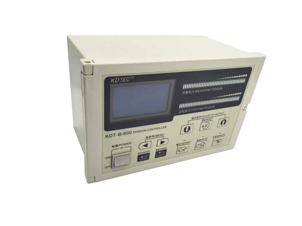
- Sensor health monitoring. The KDT-B monitors the sensor signal and defines a normal reading window of 1000–20000. A reading outside that band indicates a wiring fault, a damaged cell or a mechanical problem, and it is reported before the machine produces scrap.
- Calibration without a calibration rig. The same unit supports weight-based calibration and one-key tare, so a transducer can be verified with a known mass rather than by comparison against another machine.
- Structured terminal layout. The SJ-828 uses terminals MCC, MC1, MC2 and MC4, making field wiring legible and consistent across units of the same family.
- Protection integrated with control. On the KDT-B, Hall-based start-stop protection and limit protection are part of the control unit rather than separate safety hardware, which reduces panel size and the number of failure points.
Verifying a Delivered System
Specifications confirm what was ordered; measurements confirm what was installed. Four checks establish whether a tension control system actually performs to its specification.
- Signal integrity at the amplifier output. With the machine stationary and the web threaded at known tension, measure the amplifier output at the terminals and compare it with the expected value for the configured range and scale. A deviation here invalidates every downstream conclusion.
- Zero stability over time. Record the tare reading at power-up and again after an hour of running. Drift indicates a thermal problem in the cell, its mounting, or its wiring, and it will appear as slow tension error in production.
- Setpoint tracking across the speed range. Run the machine at minimum and maximum production speed with a fixed setpoint. The displayed and independently measured tension should both remain within the process tolerance. Divergence between the two indicates that the measuring point and the control point are not seeing the same web.
- Disturbance response. Apply a deliberate step — a splice, a roll change, or a commanded speed change — and confirm that the loop settles without sustained oscillation. A loop that oscillates only under step disturbance is over-tuned for the actual inertia, regardless of how it behaves in steady state.
A fifth check is worth adding on machines that combine tension control with edge position control: confirm that the two loops do not fight. Both act on the same web, and a correction applied by one changes the geometry seen by the other. Where both are present, sequence their commissioning and verify each with the other in automatic mode.
Applying This to a Real Specification
The chain described here maps directly onto a purchase specification. For a process requiring precise tension on a mixed-substrate line, that means a load cell rated close to the working tension, one free end on the measuring roller, an amplifier configured for the signal level the controller expects, a digital controller for repeatable setup and diagnostics, and a documented commissioning record covering the four measurements above.
Systems specified that way tend to need tuning once. Systems specified by controller model number alone tend to need tuning every time the material or the roll size changes — which, on a production line running several products, is a cost that continues long after delivery.