
Tension is not a setting you dial in once and forget. On any unwind or rewind station, the actual tension in the web is the output of a closed control loop that includes the sensor, the controller, the power stage, and the mechanical inertia of the roll itself. When a machine runs well at 30 m/min and loses register at 150 m/min, the problem is almost never the controller's brand name — it is that one element of that loop stops behaving linearly as speed rises. This article breaks the loop into four stages and shows where the practical limits sit in each one.
Stage 1: Measuring the Actual Tension
Everything downstream depends on how faithfully the measuring element reports the real web tension. In a tension amplifier paired with a load-cell tension sensor, a measuring roller is supported at one end through the load cell, and the resultant force is converted into an electrical signal that the amplifier scales to 0–10V or 4–20mA, selectable by parameter. The rated range is chosen from 15KG, 30KG, 50KG or 100KG, with bearing bores of Φ17mm or Φ25mm, both customisable to the machine.
Two mechanical details decide whether that measurement is trustworthy:
- One end of the measuring roller must be locked, and the other end must be free to extend and contract axially. If both ends are rigidly constrained, thermal growth in the shaft is converted into a bending load that the load cell reads as tension. The controller then fights an error that does not exist in the web.
- The roller mass itself is part of the measurement. During acceleration, the inertia of the measuring roller adds to the force seen by the cell. The tare function must be performed with the machine at operating temperature and the roller in its normal running position, not with a cold machine the morning after assembly.
Where the sensor is mounted matters as much as how. Mounting inside the machine frame protects the cell but complicates roller changes; outside mounting simplifies access but exposes the cell to debris and to accidental side loads during threading. Both arrangements are provided for, but the choice has to be made before the frame is drilled, not after.
Stage 2: The Control Algorithm
Once a tension signal exists, the controller compares it with the setpoint and decides what to do about the difference. The controller families on this platform differ in how aggressively they act on that error, and the differences show up as machine behaviour rather than as brochure numbers.
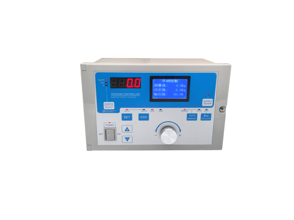
The SJ-828 uses a non-overshooting PI algorithm with acceleration and deceleration coefficient compensation. It supports constant tension and taper tension modes, and it can drive a magnetic particle clutch or brake directly from its own dual 24V / 4A outputs — no external power module is required. Supply is 220VAC with a 4A fuse. Switching between automatic and manual is seamless: a short press toggles the mode, and a long press adopts the present tension as the new setpoint. This is the behaviour operators actually care about, because it means a running machine can be re-trimmed without a stop.
The A/B shaft digital controller takes the same loop and makes it fully digital with a closed-loop PID structure. Clutch and brake output is 0–24VDC, while inverter or servo output is 0–10V. The A/B shaft switching is the feature that changes machine design rather than just machine behaviour: two winding stations can be controlled from one unit with a single button press or an external port signal, with new-roll presets, cut-off torque and preset timing all handled internally. It runs on DC24V, carries a 12-month warranty, and standard orders ship from one piece while OEM private-label orders start at 50 pieces.
| Parameter | SJ-828 | A/B shaft digital controller | KTC800A |
|---|---|---|---|
| Algorithm | Non-overshooting PI with accel / decel compensation | Fully digital closed-loop PID | PWM with four operating modes |
| Supply | 220VAC, 4A fuse | DC24V | AC180–265V wide range |
| Clutch / brake output | Dual 24V / 4A, direct drive | 0–24VDC | DC0–24V / 4A |
| Servo / inverter output | — | 0–10V | — |
| Tension modes | Constant + taper | Constant + taper, per-shaft presets | Constant current / voltage / power / external signal |
| Typical fit | Single-station film and paper | Twin-station winders | Wide-input retrofits, magnetic particle drives |
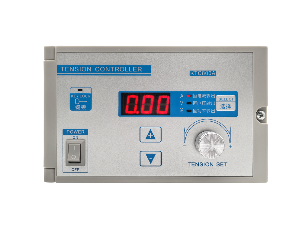
The KTC800A sits slightly apart from the other two. Its AC180–265V input range lets it drop into installations where the supply wanders, which is common on older lines and on generator-fed sites. Its four modes — constant current, constant voltage, constant power and external signal — cover drive types that a pure tension-feedback loop does not: constant power mode in particular suits magnetic particle equipment, where the relationship between coil current and transmitted torque is not linear, and it can be calibrated with a single key press.
Stage 3: The Power Stage and the Mechanics
The controller only commands. What actually converts that command into web tension is the brake or clutch, and behind it the roll. Three mechanical facts limit achievable performance no matter how good the control loop is.
- Roll inertia changes with the square of the diameter. A full roll at three times the core diameter carries nine times the inertia. A loop tuned on the core will overshoot on the full roll, and a loop tuned on the full roll will be sluggish on the core. This is exactly why taper tension exists, and why the digital controller exposes new-roll presets and cut-off torque on the A/B switch.
- Brake torque must exceed the maximum tension requirement throughout the roll life. Selecting a brake that only just meets nominal tension leaves no authority for the transient at a splice or at a commanded line-speed change.
- The sensor cannot be the stiffest element in the load path. If the frame carrying the load cell deflects more under tension than the cell itself, the reading measures frame compliance rather than web tension.
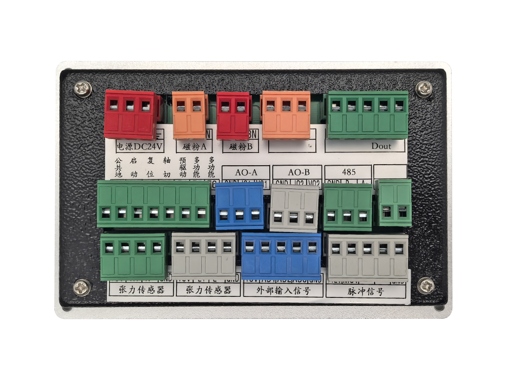
For installations where the electronics and the power section are physically separated, the PAU-4B-V split-type arrangement places signal processing at the panel and the power section near the brake. Input is AC220V 50/60Hz, output is DC0–24V at 4A, the control signal is 0–10V with a duty cycle range of 0% to 98%, and the assembly is rated for ambient temperatures up to 70°C. Plug-in terminals keep field wiring serviceable without breaking the panel.
Stage 4: Specifying and Commissioning for the Real Line
These specifications only become a working machine when they are matched to the process. The parameters worth settling before order are the maximum web tension, the minimum and maximum roll diameters, the line speed range, the acceleration the machine must sustain, and the driven element type — magnetic particle, pneumatic, or servo.
The KDT-B constant-tension controller covers the middle of that range with three modes — tension feedback, winding taper and unwinding taper — a 24V magnetic particle drive output and a 0–5V analog output for servo or torque motors. It adds the safety and serviceability features that reduce unplanned downtime: Hall-based start-stop protection, limit protection, one-key tare, sensor monitoring with a normal reading window of 1000–20000, weight-based calibration, factory reset, and a bilingual display. It is offered in horizontal, vertical and side mounting orientations, but must always use a universal bearing seat — rigid mounting is explicitly not permitted, for the same thermal reason described in Stage 1.
Commissioning then becomes a short, reproducible sequence:
- Verify mechanical compliance and roller freedom before power is applied.
- Tare at operating temperature with the web threaded and stationary.
- Enter the roll diameter limits and confirm the taper curve against the process requirement.
- Run at minimum speed, then at maximum speed, and check that the tension reading holds across the range.
- Introduce a deliberate step — a splice or a commanded speed change — and confirm the loop settles without sustained oscillation.
If a machine passes those five steps, the tension loop is sound. If it fails step five, the answer lies in Stage 3 far more often than in Stage 2. Recognising that early is what separates a retrofit that works from one that is quietly out of specification for the rest of its service life.
For lines that combine tension control with lateral position control, the two loops interact, and it is worth reading the companion engineering note on edge position control before finalising a combined specification. Machines that run packaging, printing and plastic film processes usually carry both.