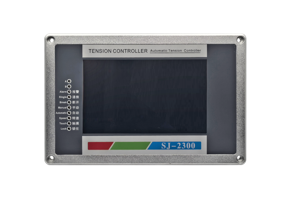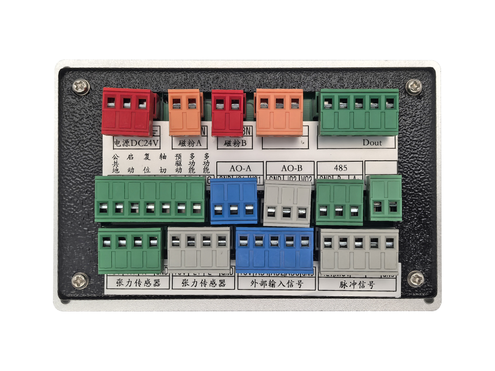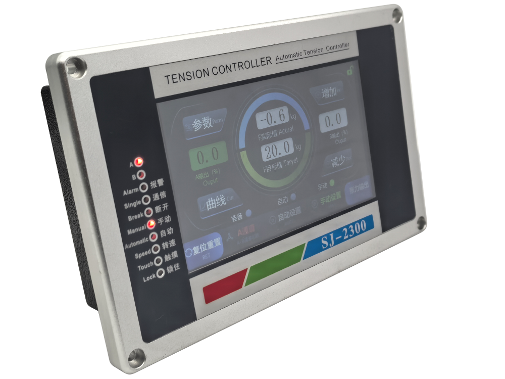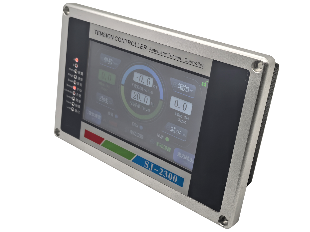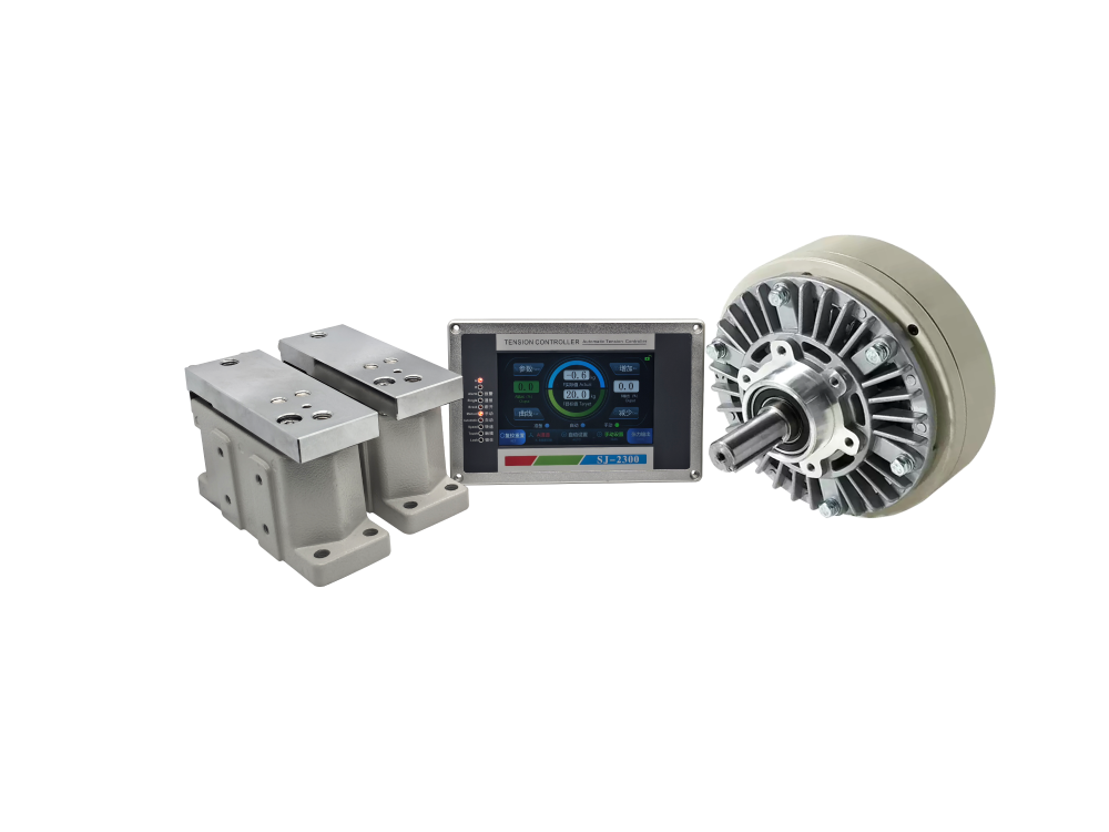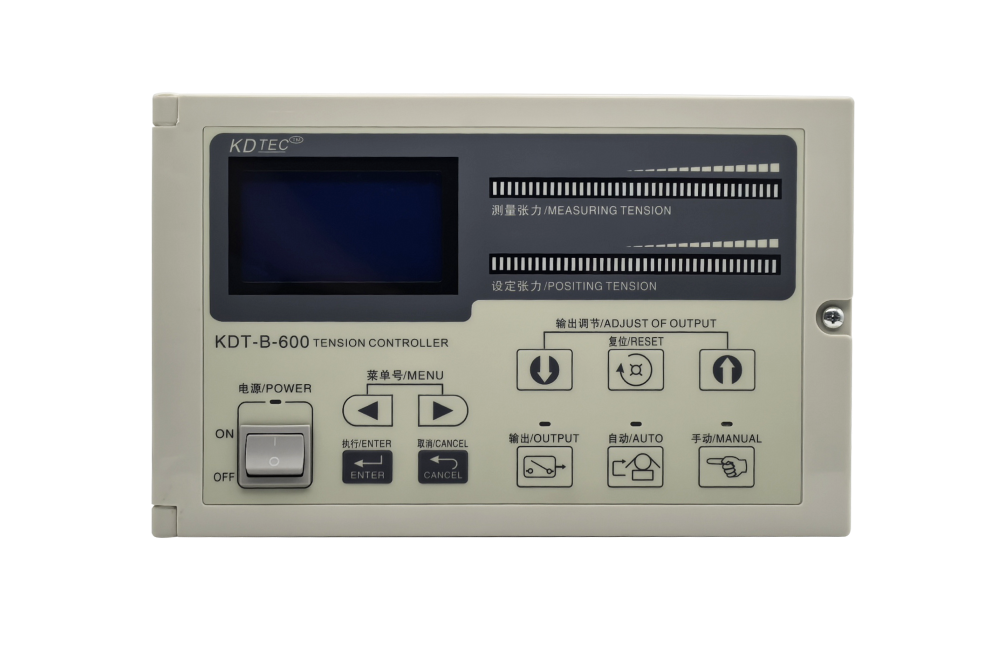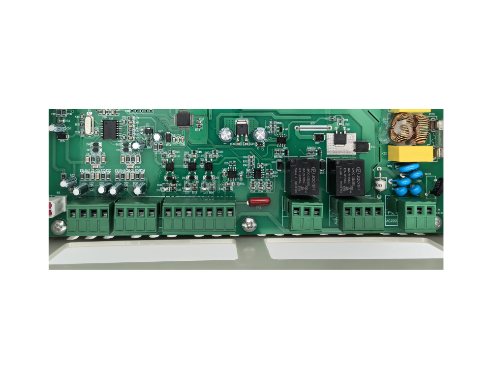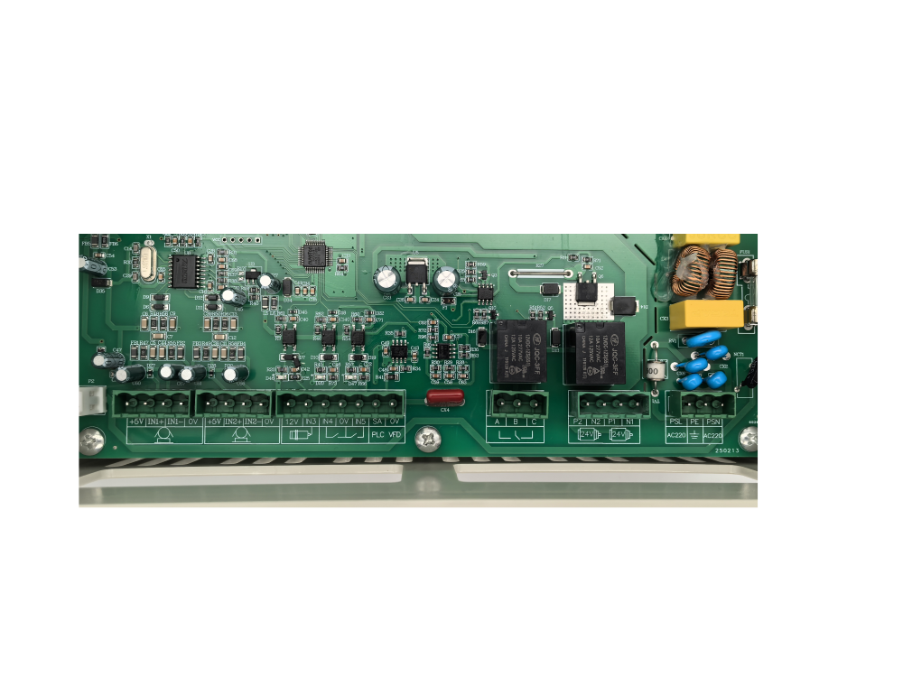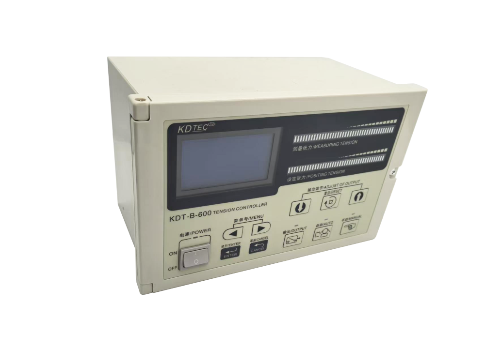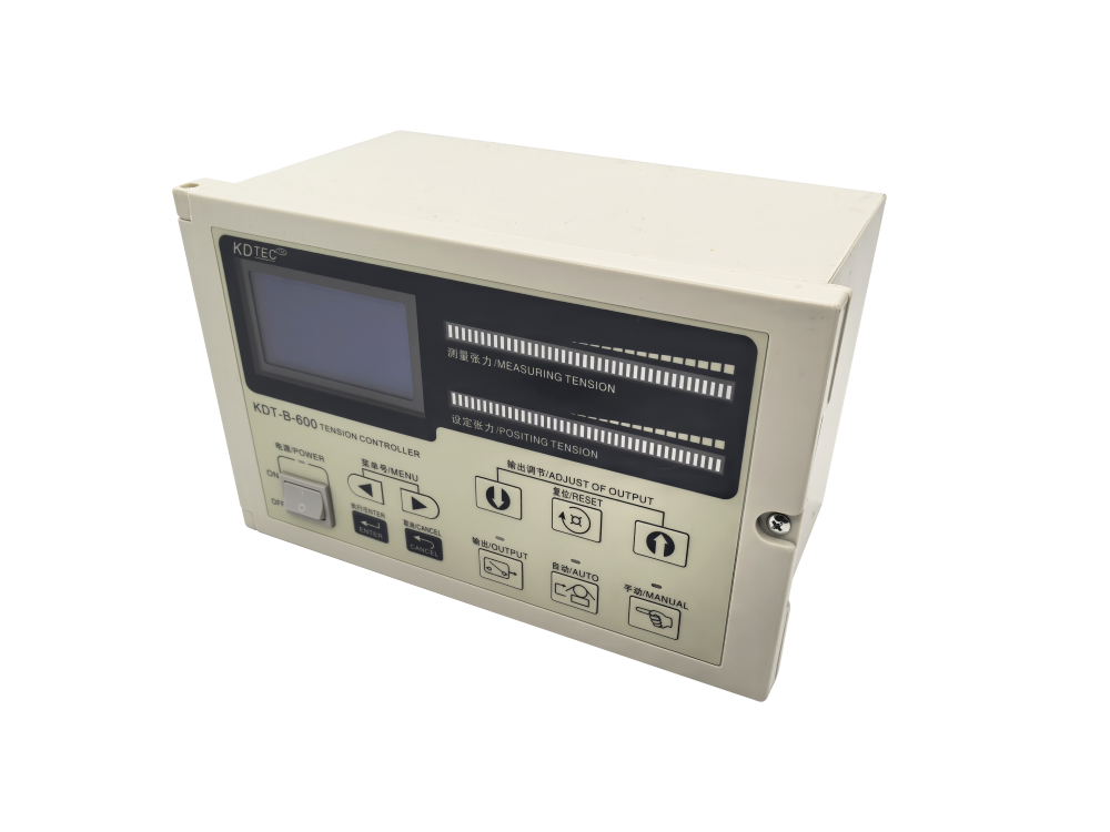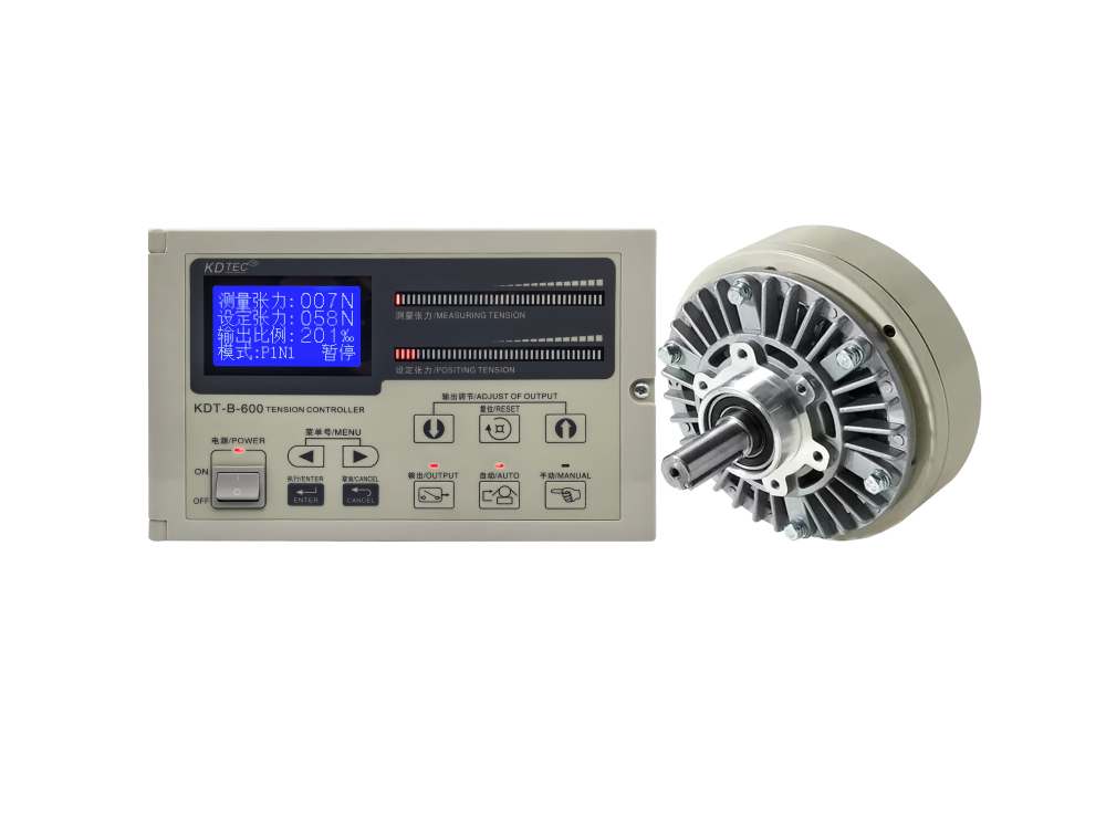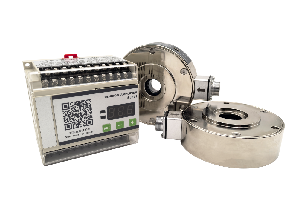
A closed-loop web tension control system should be purchased as an engineered control loop, not as an isolated controller. The tension sensors, signal conditioning, PID controller, actuator, drive output, machine start signal and roll-change logic all affect the final result. This checklist helps buyers compare suppliers and verify the delivered system with measurable tests.
1. Information to send with the request for quotation
Provide the machine type and whether control is required on unwind, rewind or both. Include material type, web width and thickness range, line-speed range, target tension range, maximum roll diameter, core diameter and normal roll-change method. Identify the actuator: magnetic powder clutch, magnetic powder brake, inverter, servo motor or torque motor.
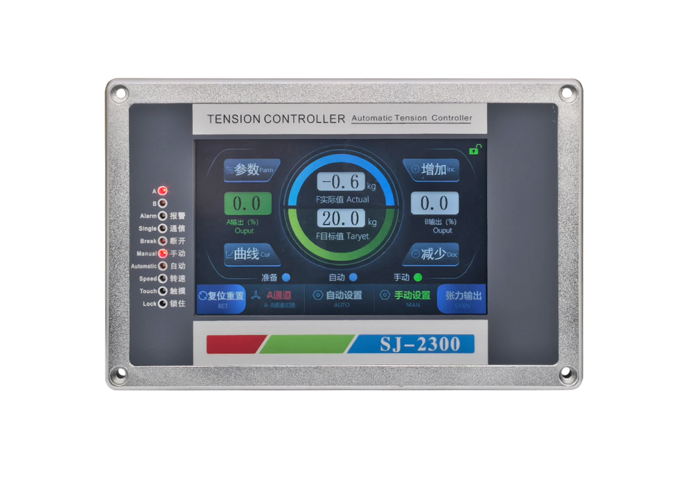
For a dual-station machine, describe the A/B shaft sequence and all available control signals. The Automatic Digital Tension Controller with A/B Shaft Switching supports closed-loop PID control, 0–24 VDC output for magnetic powder devices and 0–10 V output for inverter or servo control. Its shaft-change functions include a new-roll preset, cutting torque and preset timer. These functions are useful only when the machine sequence and wiring are defined correctly.
2. Questions for the supplier
- Which tension sensor capacity and mounting method are recommended, and why?
- What signal range does the sensor provide, and is a separate amplifier required?
- Which output will drive the selected clutch, brake, inverter or servo?
- How does the controller know that the line is running or stopped?
- What happens to output when the speed signal disappears?
- How are manual and automatic modes transferred without a tension step?
- How are A/B shaft switching, new-roll preset and cut-off torque triggered?
- Which alarm, limit and output-disable signals are available?
- What commissioning documentation and parameter backup will be supplied?
3. Inspect the tension measurement installation
The sensor installation must allow the web force to act in the intended measurement direction. Check the wrap angle, guide-roller alignment, bearing freedom and mechanical rigidity. Cables should be separated from contactors, motors and other electrical-noise sources, with shielding and grounding completed according to the wiring diagram.
Before loading material, verify that the displayed value is stable and changes in the correct direction when force is applied. Perform tare with the roller and bearing hardware installed. Then calibrate with a known weight applied through the actual web path. A calibration value entered without reproducing the real force path can look correct on the screen while remaining inaccurate in production.
4. Verify actuator and output matching
In manual mode, increase output gradually while observing the actuator response. For magnetic powder devices, confirm correct terminal wiring and adequate current capacity. For an inverter or servo drive, verify the analog range, common reference, direction and enable logic. The controller display, measured output signal and actual machine response should move consistently.
5. Test automatic control systematically
Begin at low speed with conservative PID settings. Set a realistic target tension and switch to automatic mode. The actual value should approach the target without sustained oscillation. Repeat the test during acceleration, stable running and deceleration. If the value fluctuates, investigate mechanical vibration, roller runout, sensor installation, electrical noise and filter settings before increasing controller gain.
| Test condition | What to record | Acceptance focus |
|---|---|---|
| Machine stopped | Actual tension and output | No uncontrolled output increase |
| Low-speed run | Setpoint, actual value, output | Stable response and correct direction |
| Acceleration/deceleration | Peak deviation and recovery | No web break or sustained oscillation |
| Normal production speed | Tension trend and finished roll | Repeatable quality over time |
| Emergency stop/restart | Output before and after restart | Safe stop and controlled recovery |
6. Validate A/B shaft roll change
A dual-station system must be tested with the real mechanical transfer sequence. Confirm the selected shaft, new-roll preset, timer, cutting torque and external switch inputs. Run several transfers at normal production conditions and record the actual tension before, during and after each change. If tension jumps or the web slips, adjust the preset and timing with the machine builder rather than treating it only as a PID problem.
7. Review product quality, not only the display
The controller can show a stable number while the web path still produces defects. Inspect the finished roll for telescoping, wrinkles, loose edges, excessive hardness, core slippage and inconsistent diameter build. Compare several rolls, not a single short trial. Acceptance criteria should combine the controller trend with actual product quality.
8. Documentation to receive before sign-off
- Final wiring diagram and terminal list.
- Sensor model, capacity and mounting drawing.
- Calibration procedure and the known weight used.
- Final PID, filter, taper, start and shaft-change parameters.
- Alarm and interlock logic.
- Backup of controller settings and a recovery procedure.
- Supplier contact for commissioning and troubleshooting support.
Final recommendation
A reliable tension control system is demonstrated by repeatable production results under start, stop, speed change and roll transfer—not by a stable screen value alone. Define the test plan before ordering, record the agreed acceptance criteria in the purchase specification, and verify the complete loop with the actual material.