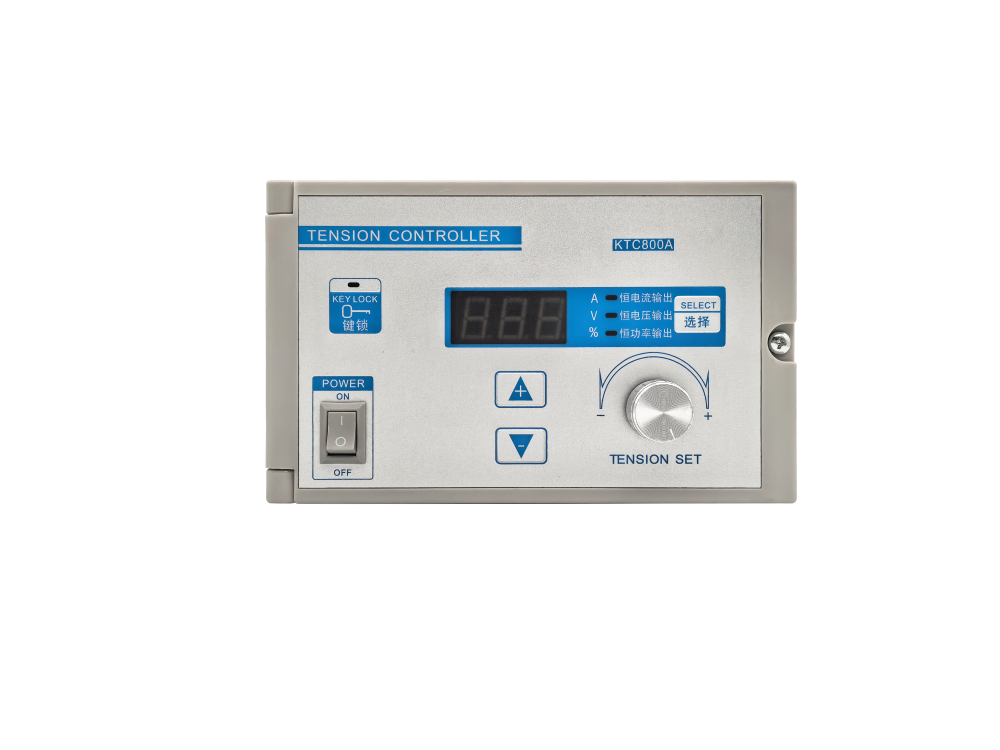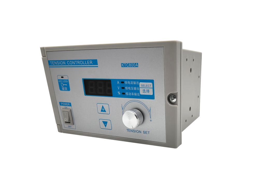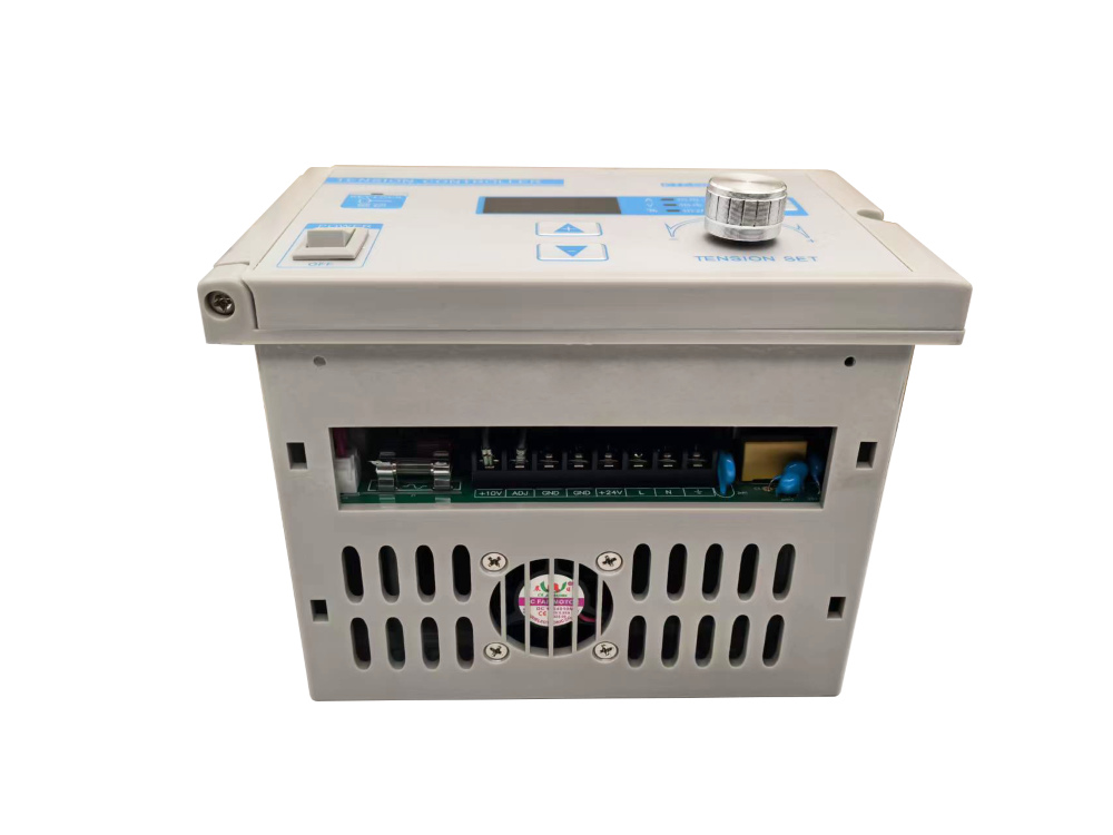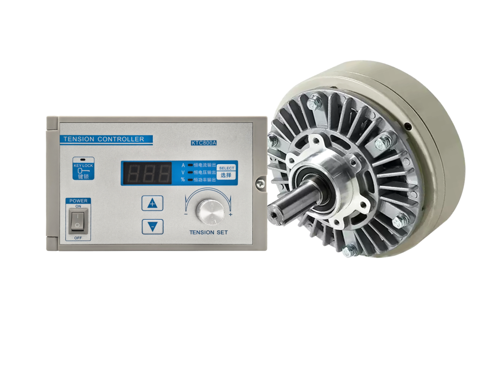
Selecting a tension control system is not simply a matter of choosing the controller with the largest display or the longest feature list. The controller must match the mechanical process, tension detector, actuator, roll-change sequence and production speed. A mismatch may still run in manual mode, but it can create unstable winding, telescoped rolls, wrinkles, web breaks or excessive commissioning time.
1. Define the process before comparing controllers
Start with the machine function: unwinding, rewinding, laminating, printing, slitting or another continuous roll-to-roll process. Record the web material, width and thickness range, normal line speed, target tension range, maximum roll diameter and whether tension should decrease as the roll builds. These values determine whether basic output control is enough or whether the line needs closed-loop feedback and taper control.
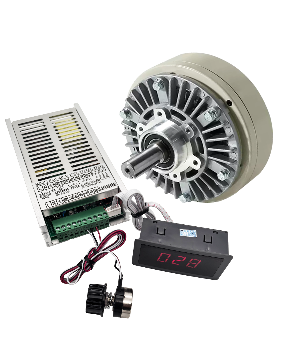
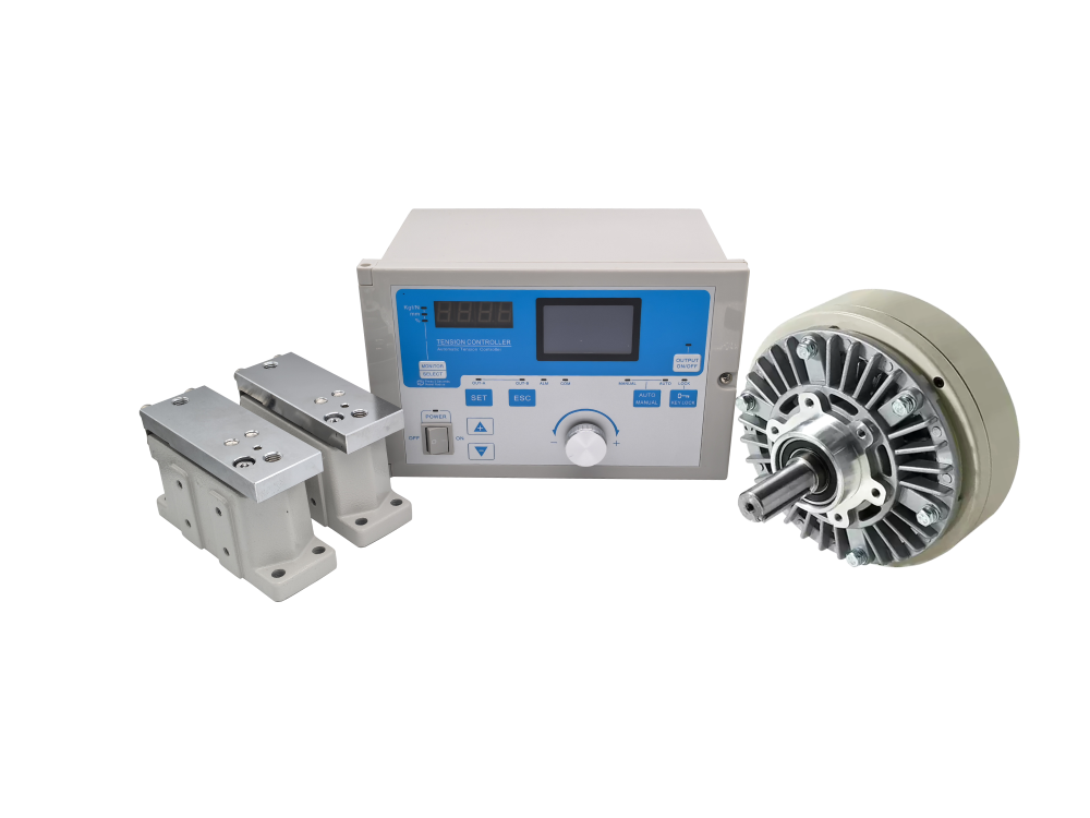
For simple applications using a magnetic powder clutch or brake, a controller such as the PAU-4B-V Split-Type Tension Controller can accept a 0–10 V control signal and provide DC 0–24 V output up to 4 A. For lines requiring measured-tension feedback, the controller must work with tension sensors and continuously correct output rather than relying only on an operator setting.
2. Choose open-loop or closed-loop control
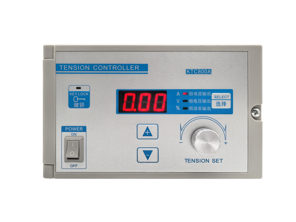
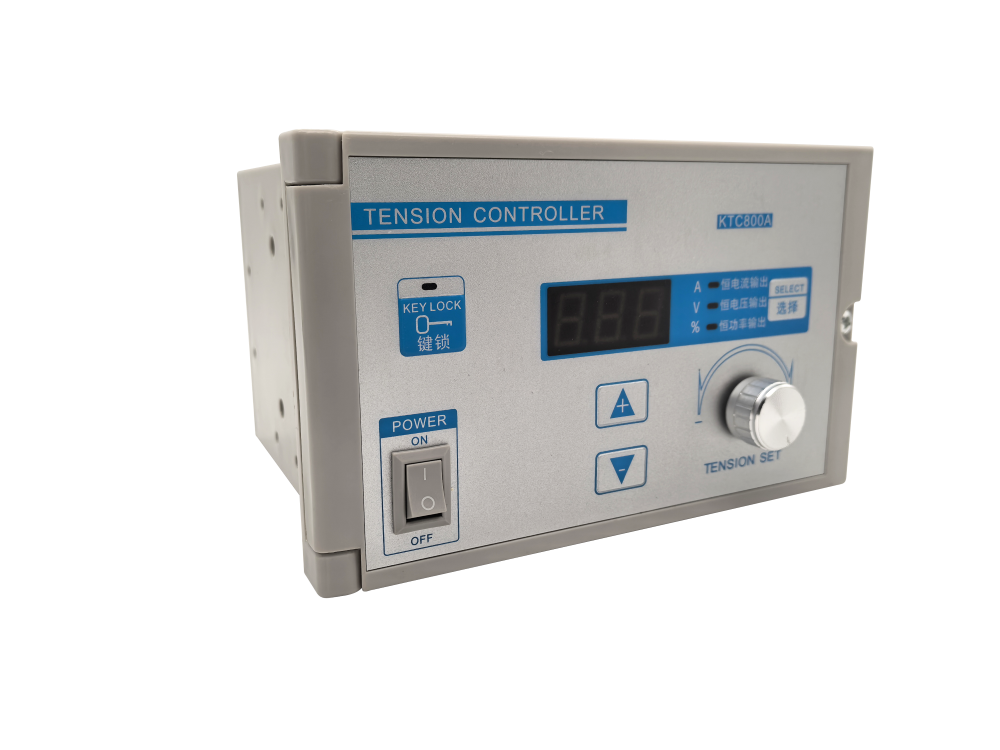
Open-loop control sets output according to a manual command, potentiometer, roll diameter estimate or external analog signal. It is economical and can be effective when material, speed and roll conditions are consistent. However, it does not directly measure the actual web tension.
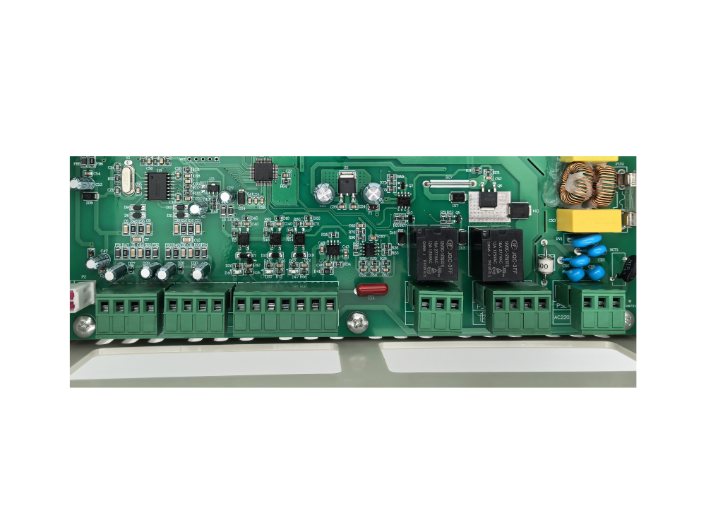
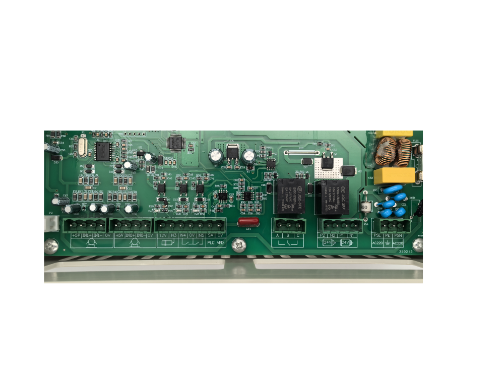
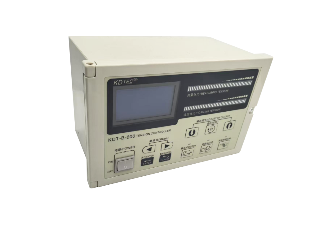
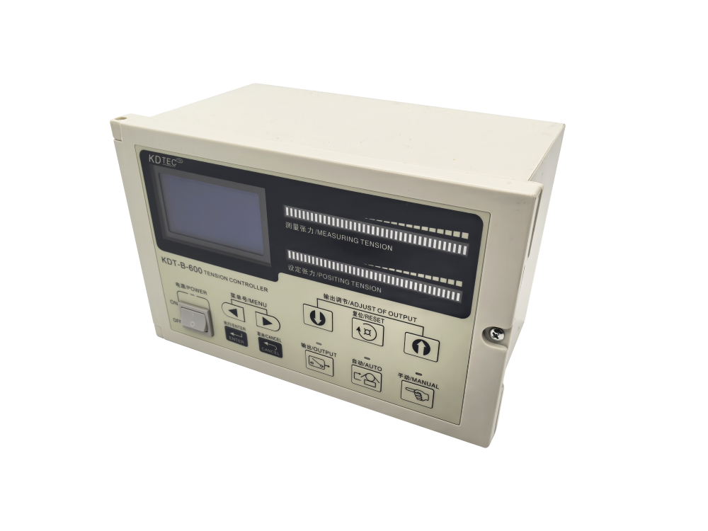
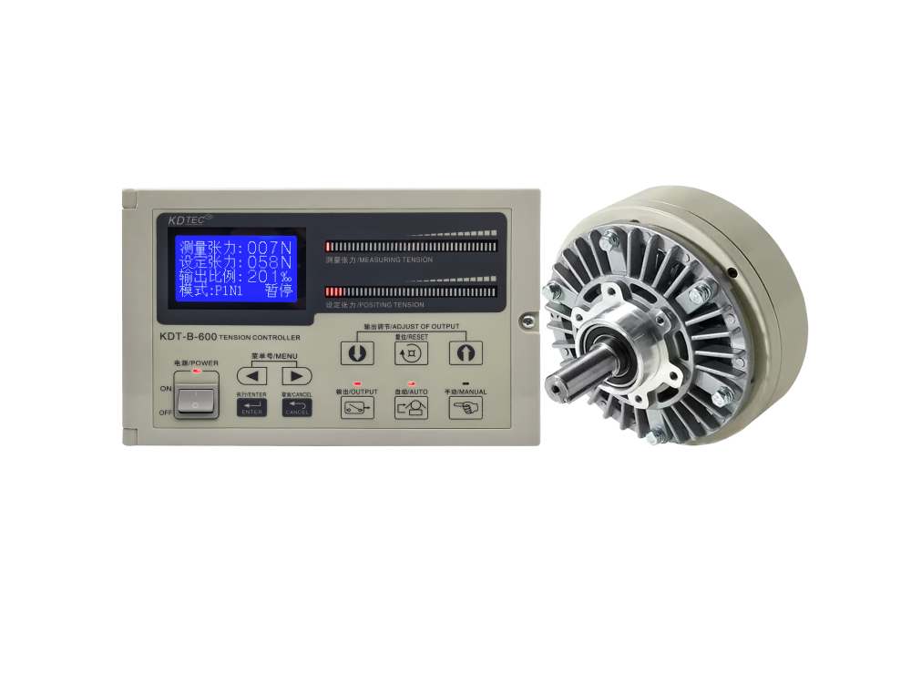
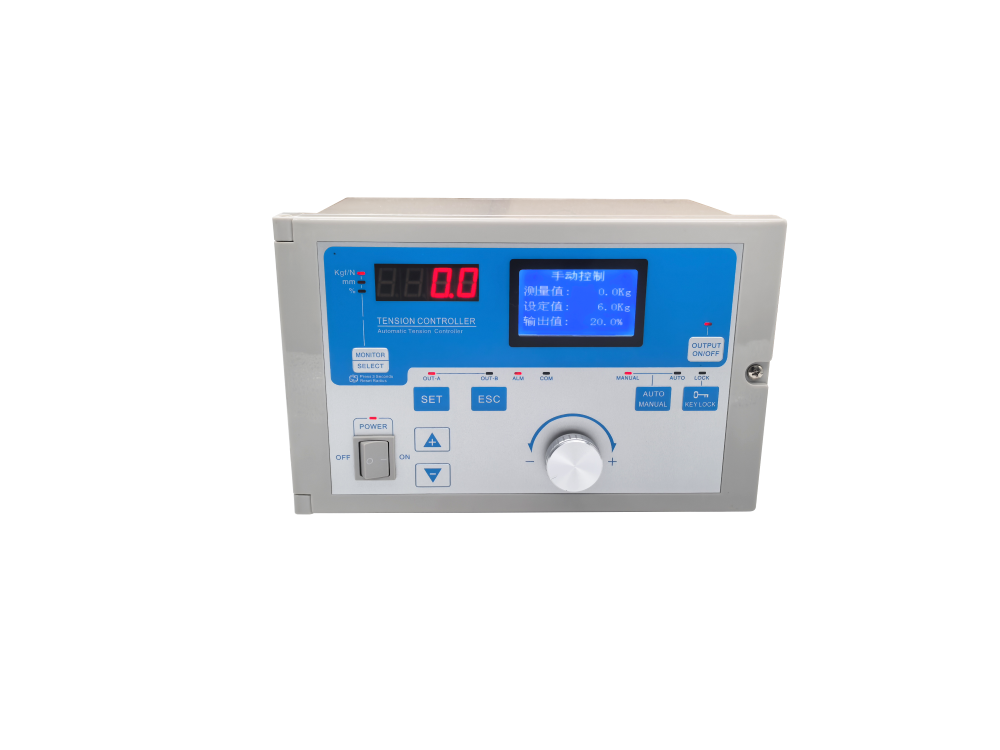
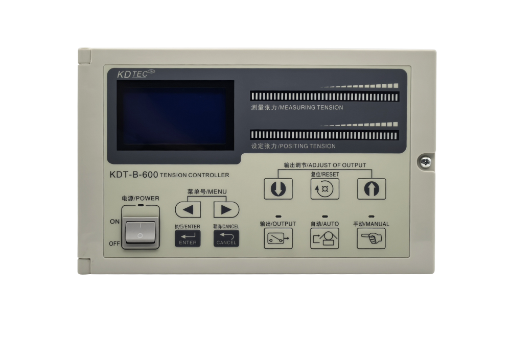
A closed-loop controller receives feedback from a tension detector, compares actual tension with the setpoint and adjusts output through PID control. It is the better choice when product quality depends on stable tension, when line speed changes, or when rolls are frequently changed. The KDT-B Automatic Constant Tension Controller supports tension feedback, winding taper control and unwinding taper control. It also provides 24 V output for magnetic powder devices and 0–5 V analog output for servo or torque motor control.
3. Match the output to the actuator
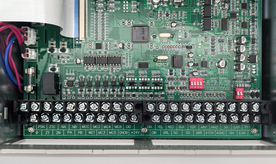
Before ordering, identify exactly what the controller will drive. Magnetic powder clutches and brakes usually require a DC current or voltage drive. Inverters and servo drives normally accept an analog command such as 0–5 V or 0–10 V. Do not assume that every tension controller supports both. Confirm the required output voltage, current capacity, signal polarity and whether the external drive needs isolation.
| Application question | Why it matters |
|---|---|
| Magnetic powder clutch or brake? | Requires a compatible DC drive output and adequate current capacity. |
| Servo motor, torque motor or inverter? | Requires the correct analog command range and start/stop logic. |
| Single station or A/B shafts? | Dual-station machines need preset outputs and a controlled transfer sequence. |
| Constant or taper tension? | Winding applications may need tension to change with roll diameter. |
4. Evaluate roll-change functions
For nonstop production with A/B shafts, ask how the controller handles the new-roll preset, cutting torque, transfer timing and external shaft-switch input. A dual-station design can shorten the transition and reduce the sudden tension change that occurs when torque transfers from the old roll to the new roll. The controller should also switch smoothly between manual and automatic modes so that commissioning adjustments do not create a tension shock.
5. Check the sensor and calibration workflow
A closed-loop system is only as reliable as its tension measurement. Confirm the number and rated capacity of the sensors, mounting direction, bearing arrangement and signal range. The machine should allow tare removal after the guide roller and bearing seats are installed. Calibration should then use a known weight applied through the actual web path. The KDT-B workflow includes sensor monitoring, one-key tare and hanging-weight calibration, which makes these checks visible during commissioning.
6. Specify protection and machine interlocks
When a line stops, a controller must not continue increasing output because it interprets the lack of measured tension as an error. Ask how the controller detects machine stop, whether it uses a Hall pulse or external start signal, and how it behaves after restart. Limit contacts, alarm outputs and output-disable inputs should be included in the electrical design rather than added after installation.
7. Use an acceptance checklist
- Verify the controller power supply and all output ranges against the actuator datasheets.
- Confirm the tension sensor signal changes smoothly and returns to zero after tare.
- Calibrate with a known weight and record the displayed value.
- Test manual mode, automatic mode and the transition between them.
- Run at low, normal and high operating speeds with the actual material.
- Test acceleration, deceleration, emergency stop and restart.
- For dual-station machines, test the full A/B shaft transfer with a real roll change.
- Document the final PID, filter, taper and preset values for future maintenance.
Final recommendation
Choose the controller from the process backward: first define tension range, actuator, sensor, speed and roll-change method; then compare control modes and protection functions. This approach is more reliable than selecting by model name alone and gives the supplier enough information to propose a correctly matched web tension control solution.