
An automatic web guiding system keeps a moving web aligned as it passes through printing, packaging, slitting, laminating and other roll-to-roll machinery. The correct system depends on what reference must be tracked, which material is being processed, how much correction travel is available and where the actuator can be installed.
1. Decide what the system must track
Edge position control (EPC) tracks the left or right edge of the material. It is the common choice when the web has a consistent edge and the goal is to keep that edge at a fixed machine position. Center position control (CPC) uses two edge references to keep the material centerline aligned. Line position control (LPC) tracks a printed line or contrast feature. State the required guiding mode before selecting a controller or sensor.
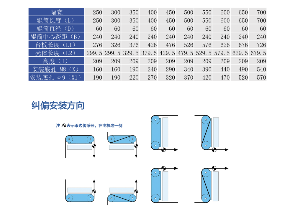
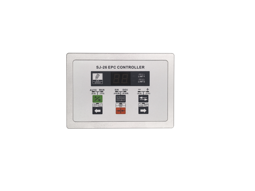
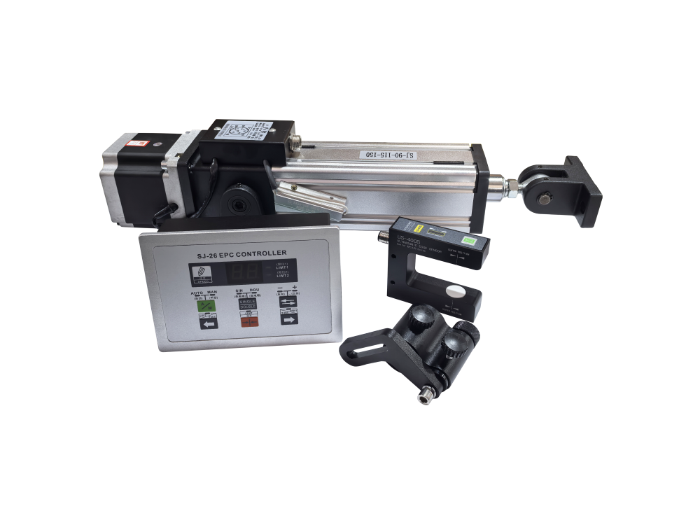
The Integrated Web Guiding Machine supports left-edge, right-edge and center guiding modes. The SJ-26 EPC Controller offers single-sensor operation for normal edge or line tracking and dual-sensor operation for more complex guiding tasks.
2. Select the sensor by material behavior
A photoelectric sensor detects changes in transmitted or reflected light. It is well suited to many opaque webs, printed lines and standard edge-tracking applications. Its performance depends on contrast, transparency, surface reflection and ambient light conditions.
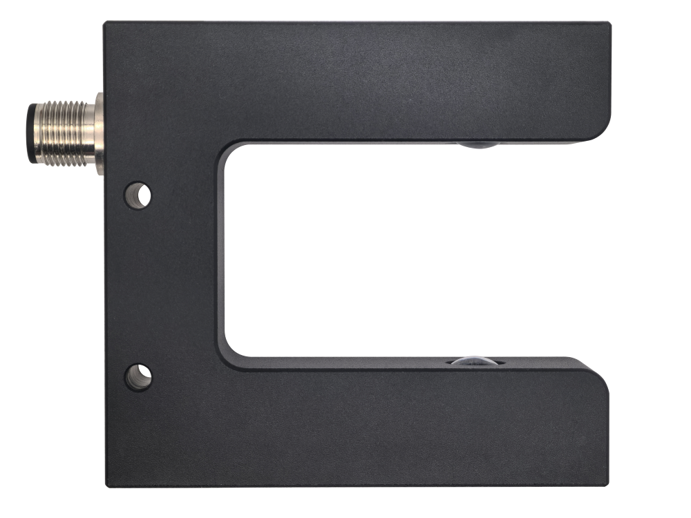
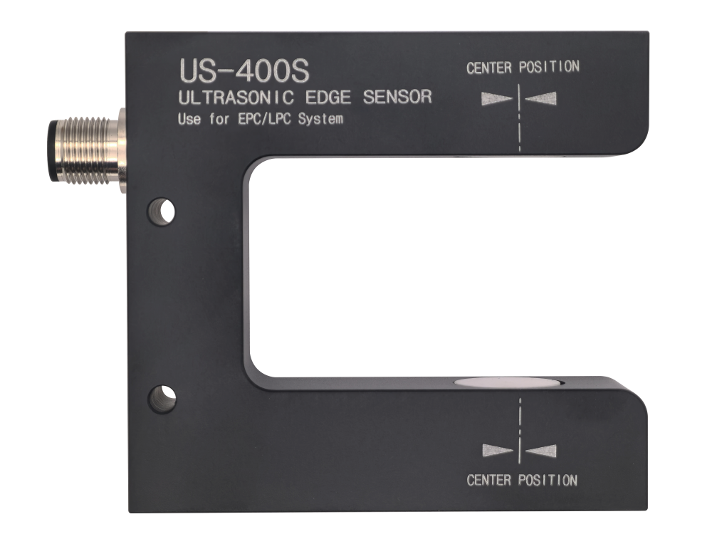
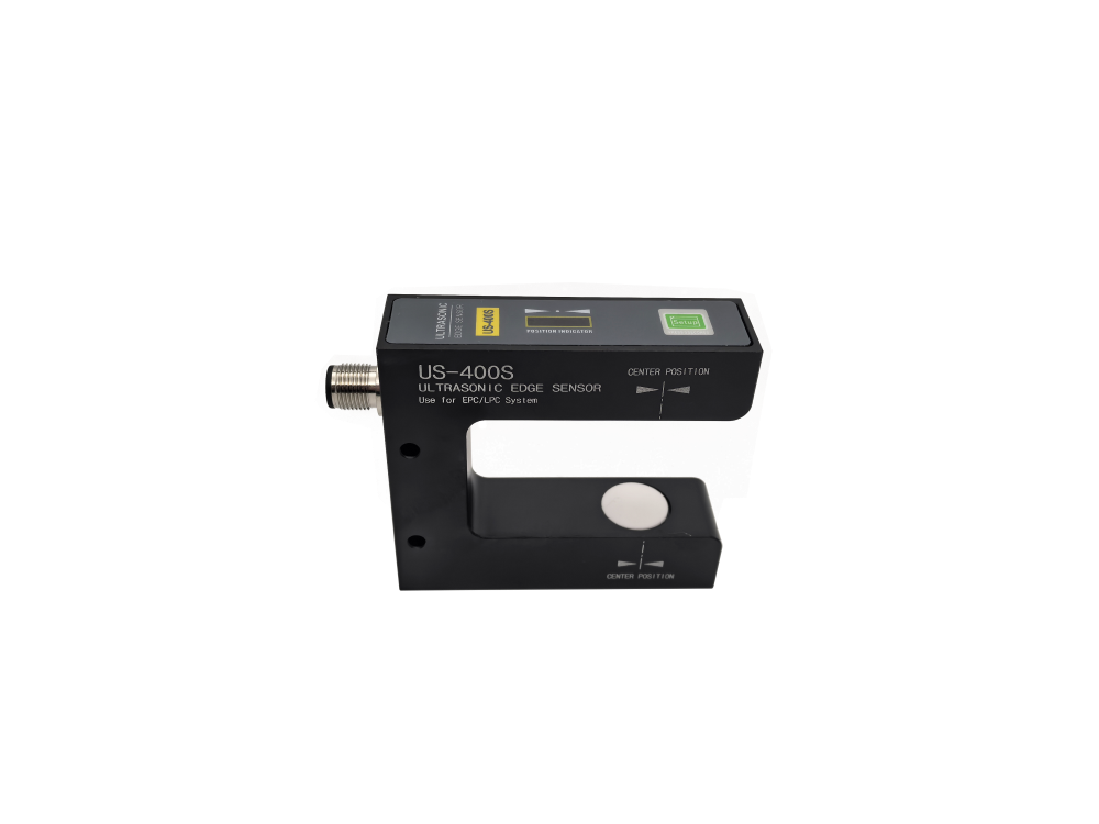
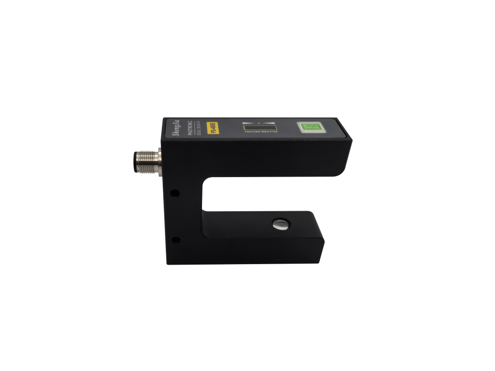
An ultrasonic sensor detects the boundary between material and air using sound rather than optical contrast. It is often preferred for transparent films, reflective materials or webs whose color changes would make optical detection unreliable. On the SJ-26 system, the PS-400S is the photoelectric option and the US-400S is the ultrasonic option.
| Material or reference | Typical sensor direction | Questions to verify |
|---|---|---|
| Opaque paper, nonwoven or stable film edge | Photoelectric or ultrasonic | Edge quality, dust, speed and required accuracy |
| Transparent or highly reflective film | Ultrasonic | Thickness range, flutter and sensor gap |
| Printed line or registration feature | Photoelectric | Color contrast, line width and background variation |
| Center guiding | Two edge sensors | Minimum and maximum web width and mounting travel |
3. Compare integrated and split systems
A split system uses separate controller, sensor, actuator, drive and guide frame components. It offers layout flexibility and can be appropriate when the machine already has a suitable guide frame or when components must be mounted in different cabinets and positions.
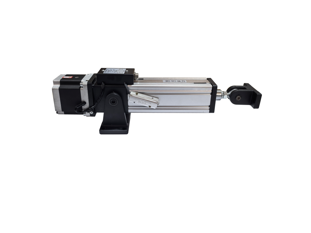
An integrated web guide combines the controller, servo drive, sensor, actuator, motor, ball screw and guide roller into one compact assembly. According to the product configuration used by SJ Auto Control, internal wiring and calibration can be completed before delivery, reducing on-site wiring and commissioning work. Integrated architecture is especially useful for machine retrofits and production lines with limited installation space.
4. Check the mechanical layout
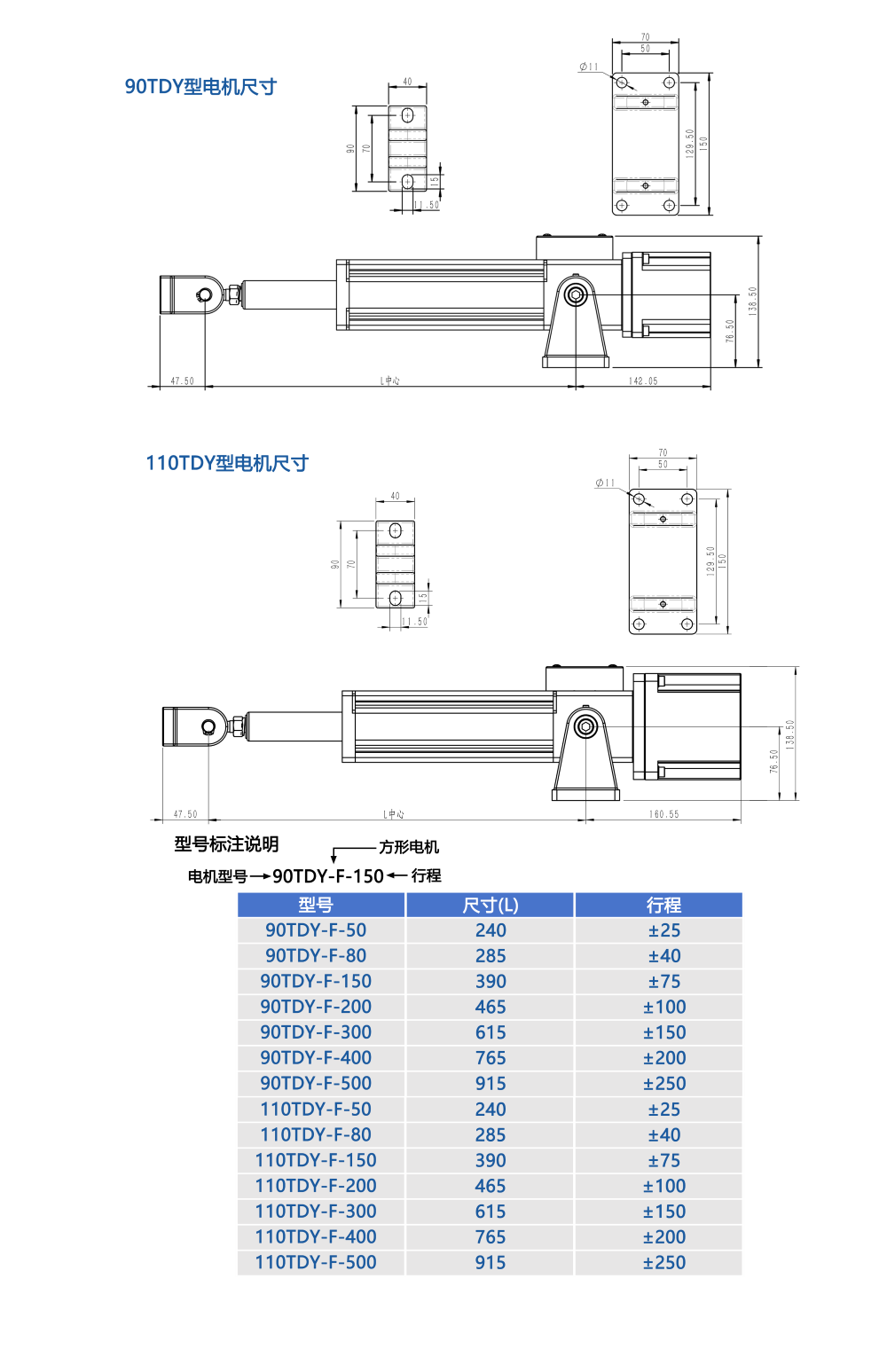
The controller cannot compensate for a poor web path. Before purchasing, provide a drawing showing the entering span, guide roller, pivot or linear actuator, exiting span and nearest fixed rollers. The supplier should confirm actuator orientation, required travel, load, web width and correction speed. Verify that the moving frame will not hit machine guards, air lines or electrical cables at either stroke limit.
5. Define control and interface requirements
- Automatic and manual modes for production, threading and maintenance.
- Center-return function for startup and material changeover.
- Adjustable response or dead band for rough edges and flexible webs.
- Limit signals for alarm or machine-stop interlock.
- Direction and polarity settings that match the installed sensor orientation.
- Power-off memory if settings must remain after the machine is shut down.
6. Run a material test before final approval
When the web is transparent, reflective, patterned, very narrow or unstable, send representative samples to the supplier. A useful test should include the slowest and fastest line speeds, the smallest and largest web widths, startup and stop, splice passage and any known edge defects. Ask for the test setup and sensor model to be recorded so the delivered system matches the evaluated configuration.
7. Acceptance checks after installation
- Confirm the sensor detects the intended edge, line or center reference across the full material range.
- Jog the actuator manually and verify the correction direction.
- Test center return and both stroke limits.
- Run automatic guiding at low speed before increasing to production speed.
- Introduce a controlled offset and verify stable recovery without repeated oscillation.
- Inspect the finished roll for edge alignment, telescoping and wrinkles.
- Save the final response, direction, dead-band and limit settings.
Final recommendation
Buy the system as a matched combination of sensor, controller and mechanics. Define EPC, CPC or line tracking first; then select the sensor for the actual material and choose integrated or split architecture according to machine layout. A clear specification and real-material test are the best protection against an edge guiding system that works on the bench but not on the production line.