SJ-26 EPC Controller + US-400S / PS-400 Sensor System

Compact Intelligent Edge Position Controller for Roll-to-Roll Material Guiding

get a quote

get a quote

If you have any questions about our product range or services, please fill out the contact form below and we will be in touch promptly
Share
  • Estimated Delivery:Aug 03 - Aug 07

  • Free Shipping & Returns: On all orders over $75

Product description
Shipping & Return

Core Features

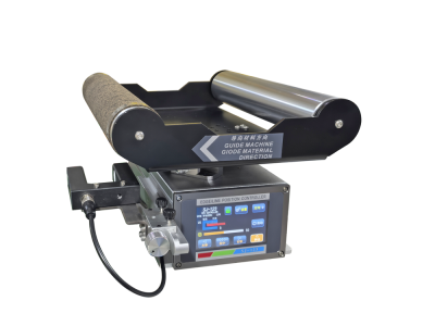
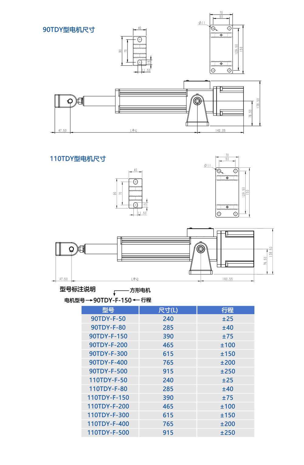
The SJ-26 EPC controller system is designed for stable roll-to-roll material guiding, offering flexible sensor compatibility, convenient operation, and reliable industrial performance.

Dual Sensor Compatibility

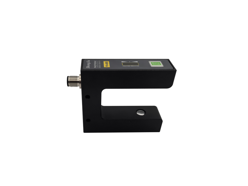
Supports PS-400S photoelectric sensor and US-400S ultrasonic sensor, allowing the system to adapt to different web materials and detection requirements.

Auto / Manual Mode

Flexible switching between automatic and manual operation makes the system suitable for continuous production, material threading, debugging, and alignment adjustment.

Single / Dual Eye Mode

Single-eye mode is suitable for edge or line tracking, while dual-eye mode is suitable for irregular printed pattern tracking and more complex material correction tasks.

Stable Industrial Control

Intelligent MCU control provides stable response, low vibration, clear operating status, and reliable correction performance for roll material processing lines.

Sensor Options

Two sensor options are available to meet different material characteristics and production environments.

US-400S Ultrasonic Sensor

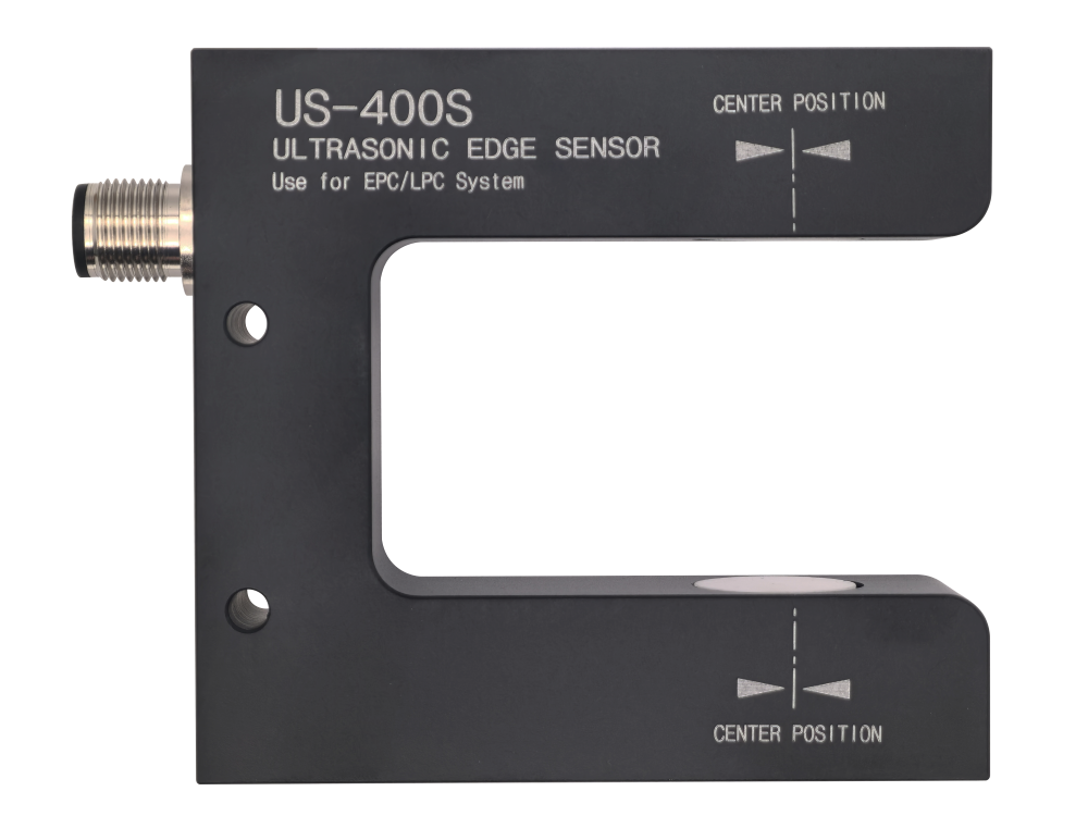
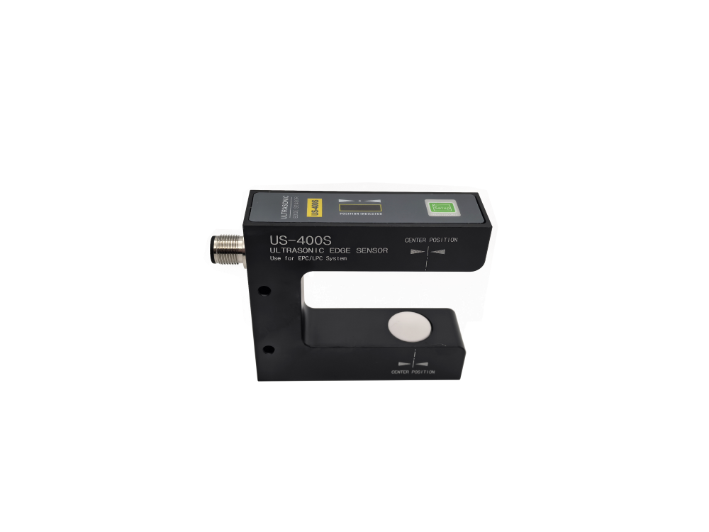
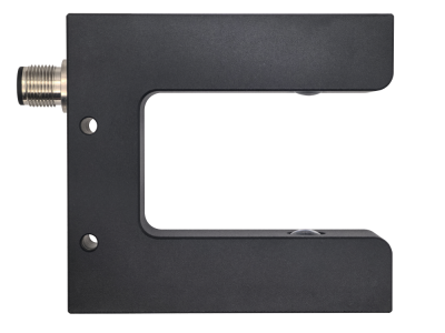
Suitable for transparent films, reflective materials, and difficult-to-detect web materials. It offers stable detection and is ideal for EPC / LPC web guiding systems.

PS-400S Photoelectric Sensor

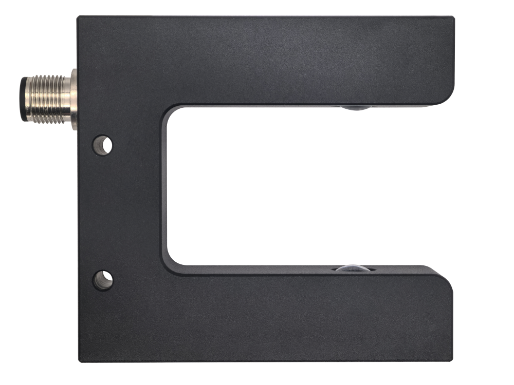
Suitable for printed line tracking, edge tracking, and standard web material detection. It provides fast response and high-precision correction for common roll-to-roll applications.

Working Principle

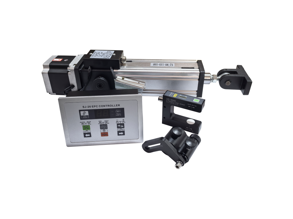
The system detects material deviation, processes the signal through the controller, and drives the actuator to complete automatic web correction.

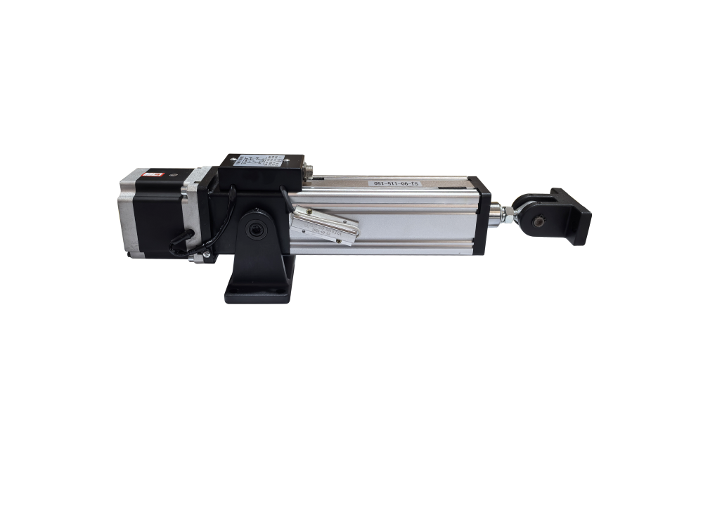
During operation, the sensor continuously detects the edge, line, or printed pattern position of the web material. When material deviation occurs, the SJ-26 controller analyzes the sensor signal and outputs correction commands to the actuator. The actuator then moves the guiding frame to keep the material aligned, helping improve production stability and finished product accuracy.

1

Detect

The sensor detects material edge, line, or pattern deviation in real time.

2

Control

The SJ-26 controller analyzes the deviation signal and outputs correction instructions.

3

Correct

The actuator adjusts the guiding frame to keep the web material running accurately.
Product FAQ

EPC Controller FAQ

This FAQ explains the application range, operation methods, parameter settings, wiring requirements, installation notes and common troubleshooting solutions for the EPC controller system.

01
Basic Functions & Compatibility
What applications is this EPC controller mainly used for, and what materials does it support?
This system works with a synchronous motor, photoelectric sensors and a ball screw actuator to automatically track and correct the position of web materials such as printed film and paper. It is widely used in printing, slitting, rewinding and other web processing production lines.
What is the difference between single-sensor and dual-sensor modes?
  • Single-sensor mode: Suitable for tracking printed lines or edge tracking of non-printed materials. It is commonly used for standard web edge or line guiding applications.
  • Dual-sensor mode: Designed for tracking irregular printed patterns, making it suitable for materials with complex patterns or without continuous edge lines.
What are the key advantages of this controller compared with traditional EPC devices?
The controller adopts intelligent single-chip microcomputer control. In single photoelectric mode, it supports 0-50 levels of response speed adjustment, effectively reducing the noise and strong vibration commonly found in traditional single-sensor guiding systems. It also supports one-touch switching between single and dual photoelectric modes, as well as flexible photoelectric polarity switching for wider material compatibility and easier operation.
02
Operation & Parameter Settings
How do I switch between automatic and manual guiding modes?
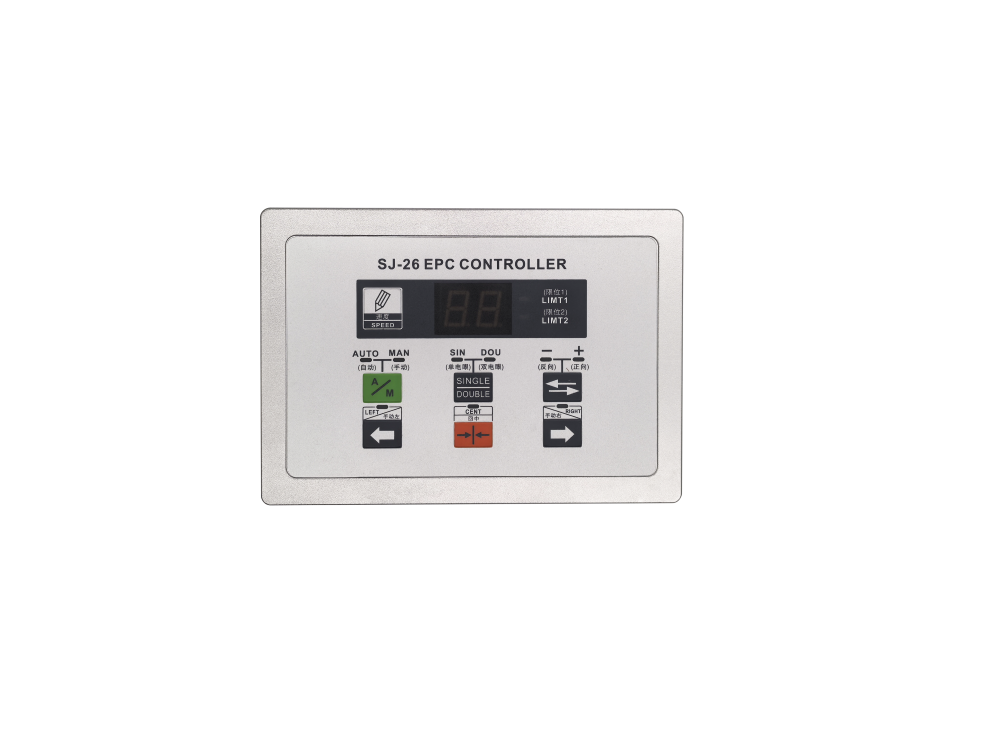
Press the A/M button on the panel to switch between automatic and manual modes:
  • Automatic mode: The forward and reverse rotation of the synchronous motor is automatically controlled by the material deviation signal detected by the photoelectric sensor.
  • Manual mode: The motor is manually controlled by the left and right jog buttons on the panel. This mode is suitable for machine debugging, material threading and position calibration.
  • Note: The left and right jog buttons can independently control motor jog operation in both automatic and manual modes.
How is the guiding response speed adjusted?
The response speed can be adjusted through the speed setting buttons on the panel. The display shows a value from 0 to 50. A higher value means a slower response, while a lower value means a faster response. Users can adjust it according to the production line speed and material stiffness.
What is the function of the center button on the panel?
After pressing the center button, the guiding actuator will automatically return to the center position of its stroke. This function is commonly used for startup reset, material changeover, debugging and post-fault reset.
What is the function of the direction selection or polarity switch?
It is used to switch the polarity of the photoelectric sensor signal, so the detection direction can match the color mark, edge line or printed pattern characteristics of the current material.
How do I operate the center-learning function?
Long press the setting button to activate center learning. The system will automatically calibrate the guiding reference position.
How do I enable or disable the power-off memory function?
Long press the manual / automatic button for 8 seconds. After hearing the beep prompt, the setting takes effect. H1 means power-off memory is enabled, and parameters will be saved after power loss. H0 means power-off memory is disabled, and parameters will not be retained after power loss.
03
Wiring & Installation
What is the power supply specification of the controller?
The controller uses AC220V power supply. The terminal is equipped with a dedicated grounding point. Reliable grounding is required during installation to ensure stable operation and electrical safety.
In single-sensor mode, can both sensor ports be used?
No. In single-sensor mode, only Sensor 1, also known as IN1, is active. Sensor 2 does not work in this mode.
What is the purpose of the limit relay output interface?
The limit relay provides normally open and normally closed contacts. It can be connected to an alarm device or linked with the production line control system. When the guiding frame reaches the stroke limit, the corresponding signal is triggered for over-limit warning or machine stop linkage.
04
Troubleshooting & Common Issues
What does it mean when the LIMIT1 / LIMIT2 indicator lights are on?
When the limit indicator light is on, it means the guiding frame has moved to one end of the effective correction range. The stroke limit protection is triggered, and the motor will stop moving further in the limit direction.
What should I check if the controller does not operate in automatic mode?
Please check the following items step by step:
  • Confirm that the controller has been switched to automatic mode and that the automatic status indicator is on.
  • Check whether the photoelectric sensor wiring is secure and whether the sensor lens is blocked by dust or oil stains.
  • Confirm that the photoelectric mode and polarity setting match the current material color mark or edge characteristics.
  • Check whether the stroke limit has been triggered and whether the limit indicator light remains on.
What should I do if the material oscillates back and forth during guiding?
Increase the response speed value properly to reduce the guiding response speed and avoid oscillation caused by overly fast correction. Also check whether the photoelectric sensor is aligned with the detection reference, and whether the mechanical screw or guide rail is stuck or worn.
What should I do if the motor can only run in one direction?
First check whether the stroke limit in the corresponding direction has been triggered and whether the related limit light is on. If the limit is normal, check whether the motor wiring is loose or has poor contact. If the motor runs normally in both directions manually but only moves one way in automatic mode, check whether the photoelectric polarity setting is reversed or whether the sensor signal is abnormal.
Shipping cost is based on weight. Just add products to your cart and use the Shipping Calculator to see the shipping price.We want you to be 100% satisfied with your purchase. Items can be returned or exchanged within 30 days of delivery.

You Might Also Like

Integrated Web Guiding Machine
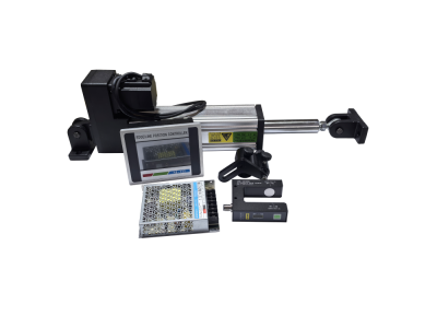
A compact, high-precision and ready-to-use automatic web guiding system for modern roll-to-roll production lines.

SJ-122 Edge / Line Position Controller System
High-Speed Brushless Servo EPC System for Precise Roll-to-Roll Web Guiding

SJ-26 EPC Controller + US-400S / PS-400 Sensor System

Compact Intelligent Edge Position Controller for Roll-to-Roll Material Guiding